HUNGARIAN
GLIDERS
1933-2000

Short history:
The Central Workshop of the Hungarian Aeronautical Association, Dunakeszi, got an assignment in 1954 to design and build a single-seat training glider, which student pilots having completed the instruction on two-seater gliders could fly, and which would serve them up to gaining the silver badge. The most important requirements were easy handling in flight, pleasant stall characteristics, greater difference between the gliding speeds for minimal sinking speed and best gliding ratio than similar category gliders usually have, however the wing load does not exceed the value of 20 kg/m2. The structure of the glider be simple, might be produced inexpensively, and as regards the production technology the facilities of the workshop prepared for building light-metal structures be utilized.
The original design got the designation A-07 and had been prepared as a constant chord three-piece wing glider with two versions of outer panels. The middle section had a span of 7,6 m, and the outer panels were 2,7 m or 3,7 m long repectively, all having the NACA 4415 airfoil section. The 13 m span variant was intended for first single-seat glider flights, and the 15 m span version would have served as a performance training glider. The fore part of the fuselage was a welded steel-tube structure covered by fabric, and the rear part was a monocoque light-metal structure. At the end of 1955 the aerodynamic and stress calculations were completed.
However in the early days of 1956 the original design concept was changed. The "one glider - two versions" idea had been kept, however two different wings - one of 13 m span for the training version and one of 15 m span for the performance training version - replaced the original wing design. The designations also changed to A-07/1 and A-07/2 respectively. The NACA 4415 airfoil section was used only for the 15 m version, and for the A-07/1 version Gö-549 airfoil section was selected. Later the designations were changed again. The A-07/1 became R-23 Gébics (Shrike) and the A-07/2 became R-24 Bibic (Lapwing). Only the Gébics version had been built, as the Workshop ceased to exist in 1958 because of an unfortunate industrial policy decision of the government.
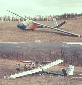
The R-23 Gébics was a shoulder wing, cantilever, V tail, light-metal glider, partly covered with fabric. All light-metal structural elements were protected by electrolyte oxidization. With its new production technology and audacious structural solutions, the R-23 Gébics became the first member of a light-metal glider family (R-23, R-24, R-25, R-26 and R-27). The prototype first flew at Jun, 1957.
The wavy light-metal skin of the wing and tail surfaces proved to be successful. The performance comparison tests flown with Gébics and Cinke (Hungarian version of the Meise Olympia) gliders had shown similar performances between 60 and 90 km/h gliding speeds. Exceeding 90 km/h the sinking speed of the Gébics was less that of the Cinke, and beyond 100 km/h the gain over the Cinke was significant.
Operational tests of the Gébics were performed in an experimental wave camp, which had been organized to explore the wave formations over the Mátra mountain range in northern Hungary. The cabin turned out to be comfortable with excellent view. Handling the glider in flight was easy, and the glider was stable at 45-50 km/h gliding speed in a 20-25° banking turn. At 70 km/h gliding speed it was easily controllable in a 50 ° banking turn. Turn reversal required 4 sec, and easy handling characterized the glider even in turbulent air. Because of these favorable characteristics the glider, after adequate preparations, was used for the experimental wave flights as well.Gébics had not been prone to spinning unintentionally in any flying attitude. It was certified for high-winch and aerotow launching, as well as spinning. However it was not certified for cloud flying and aerobatics.
In 1958 a couple of modifications were done (increased tail surfaces, modified tail surface fittings, changed angle of the V tail, modified control mechanisms). However serial production has never started.
Structure: Light-metal
Wing:
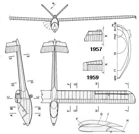
The constant chord wing had slightly rounded wingtips. The wingtips were protected by skids serving as handles as well. The airfoil section of the one spar wing was of a modified Gö-549 section with 15% thickness. The wing in front of the main spar, located in the 30% of the chord, was covered by duraluminium sheets into which waves at 150 mm span-wise distances were pressed. The main spar was a flanked duraluminium sheet. In front of the main spar the distance of ribs was 1000 - 1200 mm at locations where skin sheets were connected. Behind the main spar the wing had fabric covering. The rigidity of the wing was excellent du to the wavy skin. The Frise-type ailerons had gradually increasing gaps toward the wingtips. To control the gliding slope for landing bat-like airbrakes were fitted on the sides of the fuselage under the wing, opening upwards.
Fuselage:
The fuselage had three parts. The cabin was housed in the fore part, the rear part was of a conical shape with circle cross-section, and between these two parts was a strong main frame, enclosing the wing attachment fittings. The main structural element of the fore part was a light-metal boxed keel, which was connected to the main frame. On this keel sat the pilot's seat and in the box run the control cables and rods. The main frame was a strong, light-metal U-bar structure the upper part of which was strengthened by a welded steel-tube structure with the wing attachment fittings. The nose of the fuselage was covered by light-metal skin and was strengthened with a frame. The side of the central part of the fuselage was fabric covered. The bat-like airbrakes were housed in the side of the main frame. To disassemble/assemble the wings only one central nut had to be loosened/tightened.
The side-opening large canopy was streamlined into the contour of the fuselage. The seat was adjustable. The landing gear consisted of nose skid, a small tail skid, and a fixed, small wheel located behind the c.g. of the take-off mass glider.
The rear part of the fuselage was of a light-metal monocoque, riveted structure, built in two halves. The rivet-rows were covered by plastic band.
Tail unit:
The V tail was attached to the end of the conical form rear part of the fuselage. The angle of the V surfaces had been originally 108 degrees, however this was later changed to 90 degrees. The surfaces were foldable to vertical position after removing one central bolt, without disconnecting the control mechanism.
.jpg)

| Dimensions: |
| Wing: |
| Span, m: |
13,0 |
| Area, m2: |
13,0 |
| Aspect ratio: |
13,0 |
| Chord (root), m: |
1,0 |
| Chord (tip), m: |
1,0 |
| Airfoil (root), m: |
Gö-549 mod. |
| Airfoil (mid-span), m: |
Gö-549 mod. |
| Airfoil (tip), m: |
Gö-549 mod. |
| Dihedral, degree: |
3,0 |
| Sweep, degree: |
0 |
| Washout: |
Aerodynamic |
| Aileron: |
| Span, m: |
3,2 |
| Mean chord, m: |
0,32 |
| Total area, m2: |
1,2 |
| Balancing: |
Aerodynamic and 75% mass |
| Flap: |
| Type: |
None |
| Airbrakes: |
| Type: |
Bat-like |
| Position (upside/downside): |
Under the wing on the side of the fuselage |
| Total area, m2: |
0,6 |
| Horizontal stabilizer: |
| Span, m: |
2,5 |
| Area, m2: |
2,6 |
| Elevator: |
| Span, m: |
2,5 |
| Area, m2: |
1,15 |
| Airfoil: |
9% |
| Balancing: |
None |
| Trim: |
Yes |
| Vertical stabilizer and rudder: |
| Total area, m2: |
1,5 |
| Rudder area, m2: |
0,66 |
| Balancing: |
None |
| Fuselage: |
| Length, m: |
7,5 |
| Width, m: |
0,64 |
| Height: |
1,16 |
| Cross section, m2: |
0,61 |
| Landing gear: |
| Type: |
Fixed, unsprung |
| Wheel diameter, m: |
0,26 |
| Masses: |
| Wing, kg: |
84 |
| Fuselage, kg: |
65 |
| Tail unit, kg: |
9 |
| Empty glider, kg: |
168 |
| Gross, kg: |
264 |
| Ballast, kg: |
None |
| Wing loading, kg/m2: |
20,3 |
| Speeds: |
| VNE, km/h: |
235 |
| Max. speed with open airbrakes, km/h: |
190 |
| Max. aerotow speed, km/h: |
130 |
| Max. winch speed, km/h: |
100 |
| Max. speed in rough air, km/h: |
? |
| Stall speed, km/h: |
52 |
| Performance: |
| Min. sink, m/s (at gliding speed, km/h): |
0,85/65 |
| Best L/D (at gliding speed, km/h): |
21,1/74 |
| Start methods: |
Winch, Aerotow |

Origin of data and 3-view drawing:
Jereb Gábor: Magyar vitorlázó repülőgépek, Műszaki Könyvkiadó, 1988, Budapest
(Gábor JEREB: Hungarian Gliders, Technical Publishing House, 1988, Budapest)
Gábor FEKECS E-mail: fekecs.gabor@t-online.hu

.jpg)
